The next topic in our serie is EtherChannel. CCIE+Enterprise+Infrastructure+(v1.0+RevA)+Exam+Topics.pdf (cisco.com)
What is an EtherChannel?
Is a technique to bundle physical interfaces (Called members) into a logical one (Called Port-Channel) in order to increase the bandwidth and provide a certain redundancy in case a link fails. It also prevent the network to unused certain links to be blocked by Spanning-Tree Protocol, by acting as a single logical link.
Remark: EtherChannel offers more bandwidth, but not more throughput. The flows are always attached to one physical link, therefore the throughput of the phyisical links are the limitations for a flow.

Multi Chassis Etherchannel
There is also the possibility to bundle to switches together into a logical one and therefore offer multi chassis redundancy while configuring an EtherChannel. Switches can be connected in two ways. The first one is using dedicated stacking cables and the second one using common data interfaces. In the second case the switches are interconnected with a link that exchange control plane information. An example how this could look like:

1.1.d i LACP, PAgP, static
Negotiation of the different protocols running over a EtherChannel
The EtherChannel can have different modes: Static, LACP and PAgP. The negotiation is configured on the members of an EtherChannel (The physical links).
Mode on is for no negotiation of a protocol.
Mode Auto and or Desirable negotiate PAgP.
| Auto | Desirable | |
| Auto | Unsuccessful | Successful |
| Desirable | Successful | Successful |
Mode Active and or Passive negotiate LACP.
| Active | Passive | |
| Active | Successful | Successful |
| Passive | Successful | Unsuccessful |
Pre-requisites in order to form an EtherChannel
- Same speed among all phyisical links.
- Same duplex settings among all phyiscal links.
- Same operating mode (trunk, access, dynamic).
- If the interface is in ‚trunking mode‘, the same type of trunking and allowed VLANs should be configured.
- If the interface is in ‚access mode‘, the access vlan should be equal on all members.
- STP Cost should be equal for all VLANs among all links.
- No ports can have SPAN configured.
How to configure an EtherChannel
Let have a look how to configure an EtherChannel between two switches.
SW-1#conf t
Enter configuration commands, one per line.  End with CNTL/Z.
SW-1(config)#int range e0/0 - 1
SW-1(config-if-range)#channel-group 1 mode
SW-1(config-if-range)#channel-group 1 mode ?
  active     Enable LACP unconditionally
  auto       Enable PAgP only if a PAgP device is detected
  desirable  Enable PAgP unconditionally
  on         Enable Etherchannel only
  passive    Enable LACP only if a LACP device is detected

SW-1(config-if-range)#channel-group 1 mode active
Creating a port-channel interface Port-channel 1

SW-1(config-if-range)#
*Oct 16 18:08:40.514: %LINEPROTO-5-UPDOWN: Line protocol on Interface
Ethernet0/0, changed state to down
*Oct 16 18:08:40.515: %LINEPROTO-5-UPDOWN: Line protocol on Interface
Ethernet0/1, changed state to down
SW-1(config-if-range)#end
*Oct 16 18:08:47.673: %EC-5-L3DONTBNDL2: Et0/0 suspended: LACP
currently not enabled on the remote port.
*Oct 16 18:08:48.035: %EC-5-L3DONTBNDL2: Et0/1 suspended: LACP
currently not enabled on the remote port.
SW-1(config-if-range)#end
SW-1#
*Oct 16 18:08:50.830: %SYS-5-CONFIG_I: Configured from console by console
SW-1#
*Oct 16 18:09:09.706: %LINEPROTO-5-UPDOWN: Line protocol on Interface
Ethernet0/0, changed state to up
*Oct 16 18:09:09.706: %LINEPROTO-5-UPDOWN: Line protocol on Interface
Ethernet0/1, changed state to up
SW-1#
*Oct 16 18:09:14.606: %LINK-3-UPDOWN: Interface Port-channel1, changed
state to up
*Oct 16 18:09:15.606: %LINEPROTO-5-UPDOWN: Line protocol on Interface
Port-channel1, changed state to up
SW-1#
Based on the messages above, the logical interface Port-channel1 is up and running. we can check its status by issuing the following command.
SW-1#show etherchannel summary
Flags:  D - down        P - bundled in port-channel
        I - stand-alone s - suspended
        H - Hot-standby (LACP only)
        R - Layer3      S - Layer2
        U - in use      N - not in use, no aggregation
        f - failed to allocate aggregator

        M - not in use, minimum links not met
        m - not in use, port not aggregated due to minimum links not met
        u - unsuitable for bundling
        w - waiting to be aggregated
        d - default port

        A - formed by Auto LAG


Number of channel-groups in use: 1
Number of aggregators:           1

Group  Port-channel  Protocol    Ports
------+-------------+-----------+-----------------------------------------------
1      Po1(SU)         LACP      Et0/0(P)    Et0/1(P)

SW-1#
We can see that Po1 has the flags SU which means Layer-2 (S) and in use (U). The Members of this EtherChannel are Et0/0 and Et0/1 and bot has the flag P, that means that both are bundled into a logical interface.
How to configure a Multi-Chassis Etherchannel using Nexus VPC
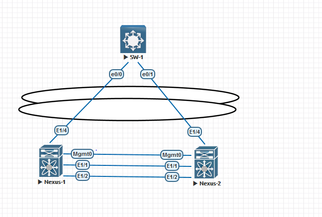
Configuring a MEC using two Nexus in a VPC looks like this. Nexus Switches in a VPC has two independtly control plane that work together by exchanging information across the vpc peer link. Therefore we must tell each Nexus that a specific EtherChannel belongs to a specific group (VPC). We can see in the CLI output above that the interface e1/4 is configured like a normal EtherChannel but the EtherChannel itself has an additional statement ‚vpc 1‘. This is configured on both VPC-Members.
Nexus-1# sh run int e1/4

!Command: show running-config interface Ethernet1/4
!Running configuration last done at: Sat Oct 16 20:19:58 2027
!Time: Sat Oct 16 20:20:41 2027

version 9.3(5) Bios:version

interface Ethernet1/4
  switchport
  channel-group 1 mode active
  no shutdown

Nexus-1# sh run int po1

!Command: show running-config interface port-channel1
!Running configuration last done at: Sat Oct 16 20:19:58 2027
!Time: Sat Oct 16 20:20:45 2027

version 9.3(5) Bios:version

interface port-channel1
  switchport
  vpc 1

Nexus-1# sh vpc brief vpc 1


vPC status
----------------------------------------------------------------------------
Id    Port          Status Consistency Reason                Active vlans
--    ------------  ------ ----------- ------                ---------------
1     Po1           up     success     success               1


Please check "show vpc consistency-parameters vpc <vpc-num>" for the
consistency reason of down vpc and for type-2 consistency reasons for
any vpc.

Nexus-1#
1.1.d ii Layer 2, Layer 3
EtherChannels can be configured as L2 or L3. L2 EtherChannels extend the broadcast domain of a network over multiple switches, while L3 EtherChannels offers connectivity and routing abilities between switches.
Configuring an L3 EtherChannel
In order to configure a L3-EtherChannel we need first to configure the physical links (Members) properly. For some reason on some platforms the phyisical links have to be define as non switchport port. See the CLI output below.
SW-1#conf t
Enter configuration commands, one per line.  End with CNTL/Z.
SW-1(config)#int range e0/2 - 3
SW-1(config-if-range)#no switchport
*Oct 16 20:34:22.648: %LINK-3-UPDOWN: Interface Ethernet0/2, changed state to up
*Oct 16 20:34:22.654: %LINK-3-UPDOWN: Interface Ethernet0/3, changed state to up
*Oct 16 20:34:23.653: %LINEPROTO-5-UPDOWN: Line protocol on Interface
Ethernet0/2, changed state to up
*Oct 16 20:34:23.662: %LINEPROTO-5-UPDOWN: Line protocol on Interface
Ethernet0/3, changed state to up
SW-1(config-if-range)#channel-group 3 mode active
Creating a port-channel interface Port-channel 3

SW-1(config-if-range)#int po3
SW-1(config-if)#no switchport
SW-1(config-if)#ip address 172.16.16.2 255.255.255.0
SW-1(config-if)#exit
SW-1(config)#exit
SW-1#ping 172.16.16.1
Type escape sequence to abort.
Sending 5, 100-byte ICMP Echos to 172.16.16.1, timeout is 2 seconds:
!!!!!
Success rate is 100 percent (5/5), round-trip min/avg/max = 1/1/1 ms
SW-1#sh ip int brief
Interface              IP-Address      OK? Method Status                Protocol
Ethernet0/0            unassigned      YES unset  up                    up
Ethernet0/1            unassigned      YES unset  up                    up
Ethernet0/2            unassigned      YES manual up                    up
Ethernet0/3            unassigned      YES manual up                    up
Port-channel1          unassigned      YES unset  up                    up
Port-channel3          172.16.16.2     YES manual up                    up
SW-1#sh arp
Protocol  Address          Age (min)  Hardware Addr   Type   Interface
Internet  172.16.16.1             0   aabb.cc80.4000  ARPA   Port-channel3
Internet  172.16.16.2             -   aabb.cc80.1000  ARPA   Port-channel3
SW-1#
1.1.d iii Load balancing
Having more bandwidth isn’t always enough. In order to support business needs, a network engineer should be able to change the load balancing methods in order to redistribute the traffic among the links. Therefore Cisco offers different methods to redistribute traffic. Something important to mention before we start redistributing our traffic over the different links is the fact that this configuration must not match on both end of the logical links. This means, that on one side of the EtherChannel you can perform load balancing based on src-mac address and on the other side you can perform load balancing using src-ip.
Modifying the load balancing method
Lets have a look on different examples

Lets ping from 192.168.1.1 towards 192.168.1.3 and see where the traffic is passing by. Based on the output below, we can appreciate that the packets are passing by only one physical port.
SW-2#sh int | include packets/sec|line
Ethernet0/0 is up, line protocol is up (connected)
  30 second input rate 212000 bits/sec, 232 packets/sec
  30 second output rate 212000 bits/sec, 232 packets/sec
Ethernet0/1 is up, line protocol is up (connected)
  30 second input rate 0 bits/sec, 0 packets/sec
  30 second output rate 0 bits/sec, 0 packets/sec
Ethernet0/2 is up, line protocol is up (connected)
  5 minute input rate 72000 bits/sec, 79 packets/sec
  5 minute output rate 72000 bits/sec, 78 packets/sec
Ethernet0/3 is up, line protocol is up (connected)
  5 minute input rate 0 bits/sec, 0 packets/sec
  5 minute output rate 0 bits/sec, 0 packets/sec
Port-channel1 is up, line protocol is up (connected)
  5 minute input rate 72000 bits/sec, 78 packets/sec
  5 minute output rate 72000 bits/sec, 78 packets/sec
SW-2#
Lets modify on SW-2 the load balancing method to ‚dst-mac‘ and try to ping now 192.168.1.2.
SW-2#sh int | include packets/sec|line
Ethernet0/0 is up, line protocol is up (connected)
  30 second input rate 100000 bits/sec, 109 packets/sec
  30 second output rate 0 bits/sec, 0 packets/sec
Ethernet0/1 is up, line protocol is up (connected)
  30 second input rate 0 bits/sec, 0 packets/sec
  30 second output rate 100000 bits/sec, 109 packets/sec
Ethernet0/2 is up, line protocol is up (connected)
  5 minute input rate 104000 bits/sec, 113 packets/sec
  5 minute output rate 104000 bits/sec, 112 packets/sec
Ethernet0/3 is up, line protocol is up (connected)
  5 minute input rate 0 bits/sec, 0 packets/sec
  5 minute output rate 0 bits/sec, 0 packets/sec
Port-channel1 is up, line protocol is up (connected)
  5 minute input rate 104000 bits/sec, 112 packets/sec
  5 minute output rate 104000 bits/sec, 112 packets/sec
SW-2#
We can observe that the request and replies are crossing different inks. But why? this is because load balancing methods can be freely choosen on both side and they do not need to match on both ends. After changing the load balancing method on SW-3, we will see that we were able to manipulate the traffic.
SW-2#sh int | include packets/sec|line
Ethernet0/0 is up, line protocol is up (connected)
  30 second input rate 0 bits/sec, 0 packets/sec
  30 second output rate 0 bits/sec, 0 packets/sec
Ethernet0/1 is up, line protocol is up (connected)
  30 second input rate 155000 bits/sec, 170 packets/sec
  30 second output rate 155000 bits/sec, 170 packets/sec
Ethernet0/2 is up, line protocol is up (connected)
  5 minute input rate 85000 bits/sec, 95 packets/sec
  5 minute output rate 85000 bits/sec, 94 packets/sec
Ethernet0/3 is up, line protocol is up (connected)
  5 minute input rate 0 bits/sec, 0 packets/sec
  5 minute output rate 0 bits/sec, 0 packets/sec
Port-channel1 is up, line protocol is up (connected)
  5 minute input rate 85000 bits/sec, 94 packets/sec
  5 minute output rate 85000 bits/sec, 94 packets/sec
SW-2#
Now traffic for each IP will choose a different link.
1.1.d iv EtherChannel Misconfiguration Guard
The name of the feature already tell us what is going to happen. In case a link has been misconfigured the interfaces will enter into errdisable state and will only recover if we issue the ’shut/no shut‘ command or errordisable recovery is configured.
For spanning-tree an EtherChannel is considered as a single link and therefore only one BPDU will be sent across the link. But over which link will this BPDU sent? This is based on the load-balancing method choosen for non-IP frames.
Conclusion
EtherChannels are in my modest opinion a great thing. It is not only the fact that they simplify networks by eliminating spanning-tree but also increase the bandwidth and offers at the same time redundancy by enabling active/active use of the links.
